| Home | Accessory Kit | Marsh CD Collection | Contact Us | Library |
Photo Gallery of the
1938 to 1939 Rife Ray #5 or
Beam Ray Clinical Rife Machine
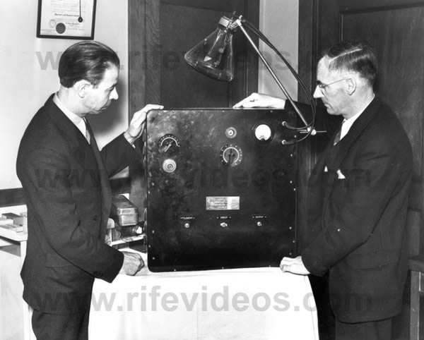 |
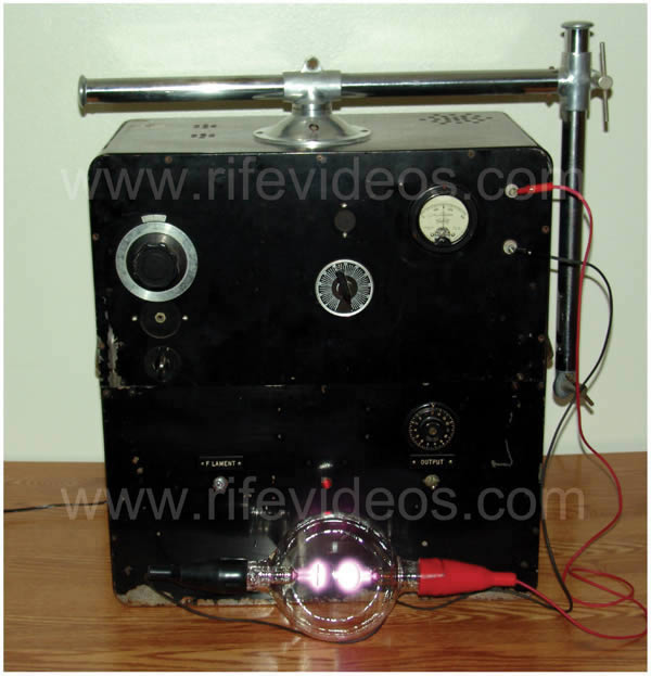
The photo, shown above, is a 1938 photo of Dr. Rife and his engineer, Philip Hoyland, with the Rife Ray #5 or Beam Ray Clinical machine. This was the machine that was built by Beam Ray Corporation. This machine was the only commercial instrument which was sold to medical doctors. They put this machine into two different cases that we know of. The one above was a portable unit and the other style was in a full case that stood about 5 feet tall and had wheels so that it could be move around.
The next photo, shown below, is of the original Beam Ray Clinical machine obtained from Dr. Larry Low. This is the only known surviving original instrument. It was this original instrument that made it possible to know how Philip Hoyland developed a machine that worked on harmonic sidebands.
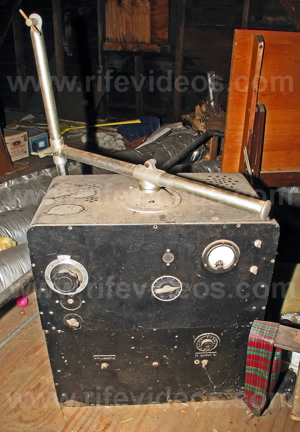
The next photo, shown below, is of the original Beam Ray Clinical machine when we first obtained it from Dr. Larry Low. It had been stored in an attic for over 25 years.
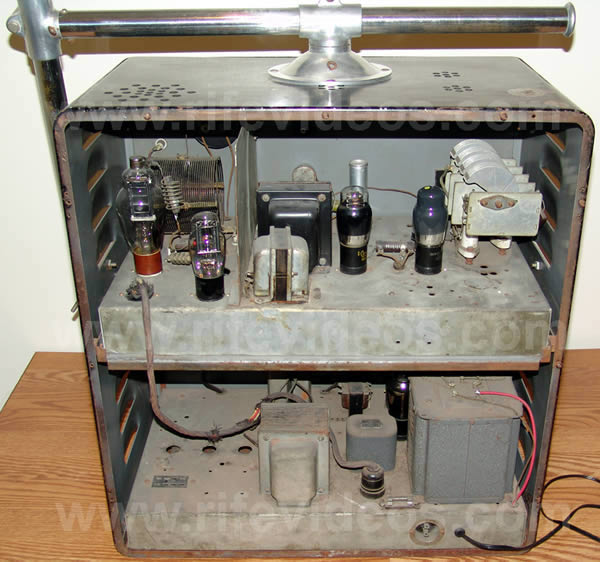
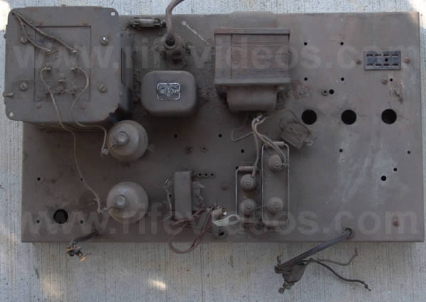
The next photo, shown below, is of the inside of the Rife Ray #5 or Beam Ray Clinical instrument. The RF tank coil was set at 3.80 MHz. The 809 vacuum tube was the main RF output power tube. There were two 866 rectifier vacuum tubes. Like all of the original Rife Ray #5 or Beam Ray Clinical machines the old RC (resistor capacitor) audio oscillators were replace with the newer patented Hewlett-Packard audio oscillator which was a more stable and accurate audio oscillator.
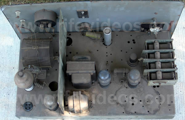
The next photo, shown below, is a top view of the audio oscillator section and the RF tank coil section. This is a photo of how the instrument looked when we first opened it up. You can see all the dust which had accumulated over the past 40 years. The doctor who originally owned it died back in 1965. All photos on this page which have this dust covering the components were taken when we first obtained the instrument. The rest of the photos which do not have this dust were taken later after we had cleaned and repaired the instrument. There was only one resistor which was burned out that needed to be replaced in order for this machine to become fully operational again. The 809 vacuum tube still worked but its output was weak so it was replaced.
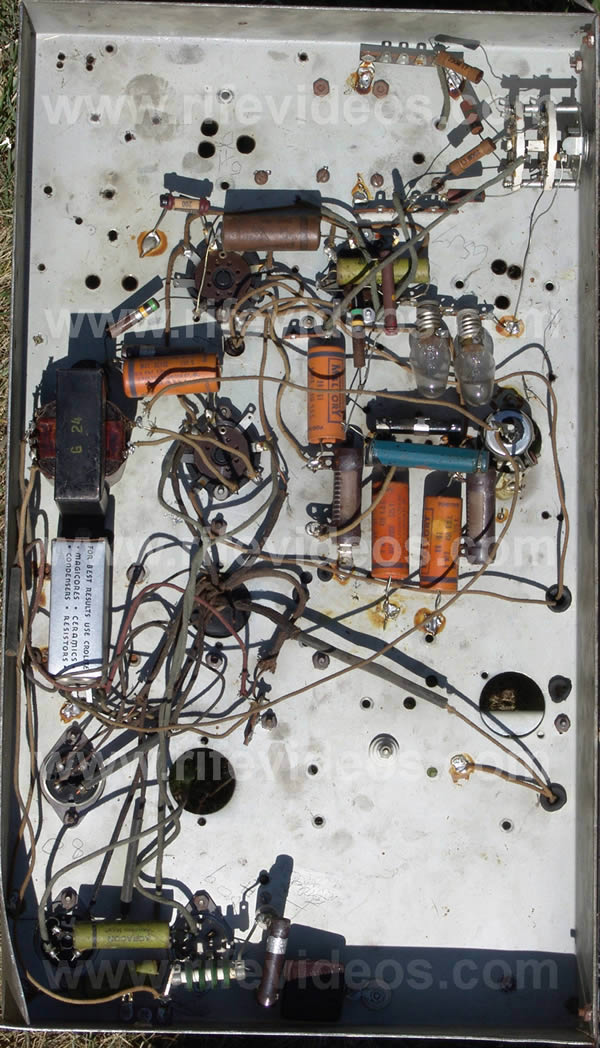
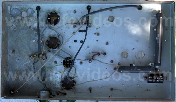
The next photo, shown below, is the under side of the RF section and audio oscillator chassis.
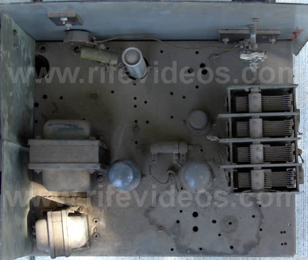
The next photo, shown below, is a closer top view look at the audio oscillator section.
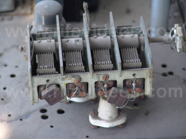
The next photo, shown below, is of the variable tuning capacitor for the audio oscillator
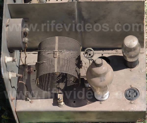
The next photo, shown below, is a closer top view look at the RF oscillator section showing the tank coil and 809 vacuum tube.
The next photo, shown below, is a top view of the high voltage power transformer, capacitors, choke and the two 866 rectifier vacuum tubes.
The last photo, shown below, is an under side view of the high voltage power transformer, capacitors, choke and the two 866 rectifier vacuum tubes.
If you would like to know more about this instrument then read Chapter 9 of The Rife Machine Report.